Reserve definition tutorial
This tutorial provides a step-by-step guide to include reserve requirements in a simple energy system with Spine Toolbox for SpineOpt.
Introduction
Welcome to our tutorial, where we will walk you through the process of adding a new reserve node in SpineOpt using Spine Toolbox. To get the most out of this tutorial, we suggest first completing the Simple System tutorial, which can be found here.
Reserves refer to the capacity or energy that is kept as a backup to ensure the power system's reliability. This reserve capacity can be brought online automatically or manually in the event of unforeseen system disruptions such as generation failure, transmission line failure, or a sudden increase in demand. Operating reserves are essential to ensure that there is always enough generation capacity available to meet demand, even in the face of unforeseen system disruptions.
Model assumptions
- The reserve node has a requirement of 20MW for upwards reserve
- Power plants 'a' and 'b' can both provide reserve to this node
Guide
Entering input data
- Launch the Spine Toolbox and select File and then Open Project or use the keyboard shortcut Ctrl + O to open the desired project.
- Locate the folder that you saved in the Simple System tutorial and click Ok. This will prompt the Simple System workflow to appear in the Design View section for you to start working on.
- Select the 'input' Data Store item in the Design View.
- Go to Data Store Properties and hit Open editor. This will open the database in the Spine DB editor.
In this tutorial, you will learn how to add a new reserve node to the Simple System.
Creating objects
- Always in the Spine DB editor, locate the Object tree (typically at the top-left). Expand the [root] element if not expanded.
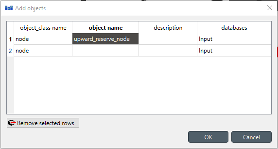
- Right-click on the node class, and select Add objects from the context menu. The Add objects dialog will pop up.
- Enter the names for the new reserve node as seen in the image below, then press Ok. This will create a new object of class node, called reserve_upward_node.
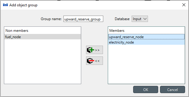
- Right-click on the node class, and select Add object group from the context menu. The Add object group dialog will pop up. In the Group name field write reserve_upward_group to refer to this group. Then, add as a member of the group the nodes electricity_node and reserve_upward_node, as shown in the image below; then press Ok.
In SpineOpt, groups of nodes allow the user to create constraints that involve variables from its members. Later in this tutorial, the group named reserve_upward_group will help to link the flow variables for electricity production and reserve procurement.
Establishing relationships
- Always in the Spine DB editor, locate the Relationship tree (typically at the bottom-left). Expand the root element if not expanded.
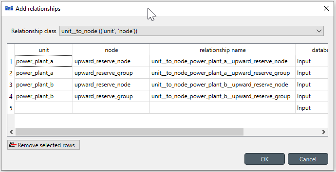
- Right-click on the unit__to_node class, and select Add relationships from the context menu. The Add relationships dialog will pop up.
- Select the names of the two units and their receiving nodes, as seen in the image below; then press Ok. This will establish that both power_plant_a and power_plant_b release energy into both the reserve_upward_node and the reserve_upward_group.
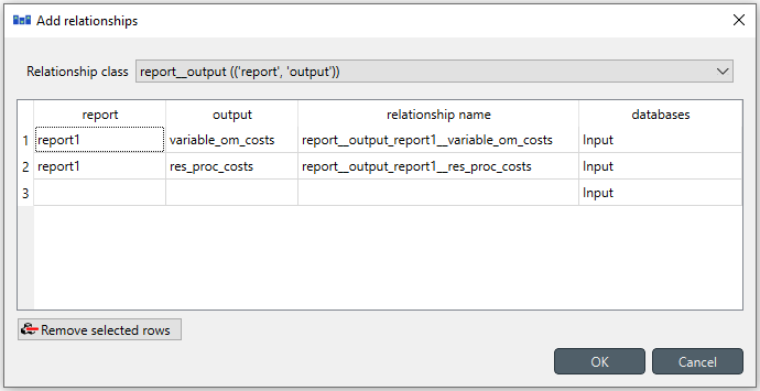
Right-click on the report__output class, and select Add relationships from the context menu. The Add relationships dialog will pop up.
Enter report1 under report, and
variable_om_costsunder output. Repeat the same procedure in the second line to add theres_proc_costsunder output as seen in the image below; then press Ok. This will write the total vom_cost and procurement reserve cost values in the objective function to the output database as a part of report1.
Specifying object parameter values
- Back to Object tree, expand the node class and select reserve_upward_node.
- Locate the Object parameter table (typically at the top-center).
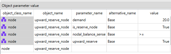
- In the Object parameter table (typically at the top-center), select the following parameter as seen in the image below:
- demand parameter and the Base alternative, and enter the value 20. This will establish that there's a demand of '20' at the reverse node.
- reserve_active parameter and the Base alternative, and enter the value True. This will establish that it is a reverse node.
- reserve_upward parameter and the Base alternative, then right-click on the value cell and then, in the context menu, select 'Edit...' and select the option True. This will establish the direction of the reserve is upwards.
- balance_sense parameter and the Base alternative, and enter the value $\geq$. This will establish that the total reserve procurement must be greater or equal than the reserve demand.
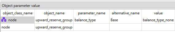
Select reserve_upward_group in the Object tree.
In the Object parameter table, select the balance_type parameter and the Base alternative, and enter the value none as seen in the image below. This will establish that there is no need to create an extra balance between the members of the group.
Specifying relationship parameter values
In Relationship tree, expand the unit__to_node class and select power_plant_a | reserve_upward_node.
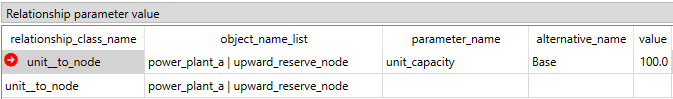
In the Relationship parameter table (typically at the bottom-center), select the capacity_per_unit parameter and the Base alternative, and enter the value 100 as seen in the image below. This will set the capacity to provide reserve for power_plant_a.
The value is equal to the unit capacity defined for the electricity node. However, the value can be lower if the unit cannot provide reserves with its total capacity.
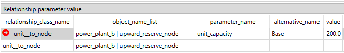
In Relationship tree, expand the unit__to_node class and select power_plant_b | reserve_upward_node.
In the Relationship parameter table (typically at the bottom-center), select the capacity_per_unit parameter and the Base alternative, and enter the value 200 as seen in the image below. This will set the capacity to provide reserve for power_plant_b.
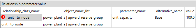
In Relationship tree, expand the unit__to_node class and select power_plant_a | reserve_upward_group.
In the Relationship parameter table (typically at the bottom-center), select the following parameter as seen in the image below:
- capacity_per_unit parameter and the Base alternative, and enter the value 100. This will set the total capacity for power_plant_a in the group.
In Relationship tree, expand the unit__to_node class and select power_plant_b | reserve_upward_group.
In the Relationship parameter table (typically at the bottom-center), select the following parameter as seen in the image below:
- capacity_per_unit parameter and the Base alternative, and enter the value 200. This will set the total capacity for power_plant_b in the group.
When you're ready, save/commit all changes to the database.
Executing the workflow
Go back to Spine Toolbox's main window, and hit the Execute project button from the toolbar. You should see 'Executing All Directed Acyclic Graphs' printed in the Event log (at the bottom left by default).
Select the 'Run SpineOpt' Tool. You should see the output from SpineOpt in the Julia Console after clicking the object activity control.
Examining the results
Select the output data store and open the Spine DB editor. You can already inspect the fields in the displayed tables or use a pivot table.
For the pivot table, press Alt + F for the shortcut to the hamburger menu, and select Pivot -> Index.
Select
report__unit__node__direction__stochastic_scenariounder Relationship tree, and the first cell under alternative in the Frozen table.Under alternative in the Frozen table, you can choose results from different runs. Pick the run you want to view. If the workflow has been run several times, the most recent run will usually be found at the bottom.
The Pivot table will be populated with results from the SpineOpt run. It will look something like the image below.
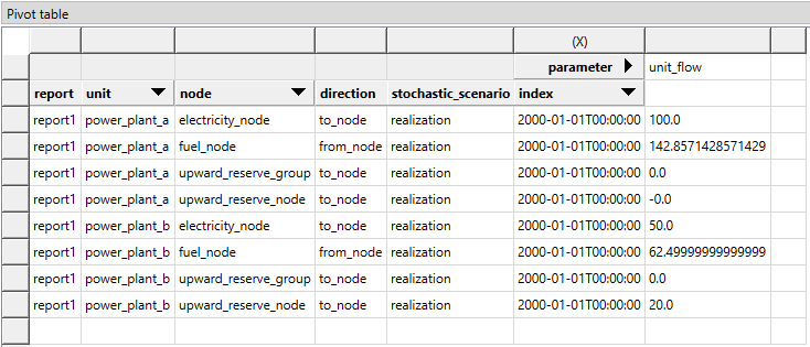
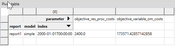
As anticipated, the power_plant_b is supplying the necessary reserve due to its surplus capacity, while power_plant_a is operating at full capacity. Additionally, in this model, we have not allocated a cost for reserve procurement. One way to double-check it is by selecting model__report under Relationship tree and look at the costs the Pivot table, see image below.
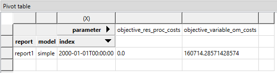
So, is it possible to assign costs to this reserve procurement in SpineOpt? Yes, it is indeed possible.
Specifying a reserve procurement cost value
In Relationship tree, expand the unit__to_node class and select power_plant_a | reserve_upward_node.
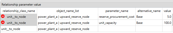
In the Relationship parameter table (typically at the bottom-center), select the reserve_procurement_cost parameter and the Base alternative, and enter the value 5 as seen in the image below. This will set the cost of providing reserve for power_plant_a.
In Relationship tree, expand the unit__to_node class and select power_plant_b | reserve_upward_node.
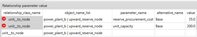
In the Relationship parameter table (typically at the bottom-center), select the reserve_procurement_cost parameter and the Base alternative, and enter the value 35 as seen in the image below. This will set the cost of providing reserve for power_plant_b.
Don't forget to commit the new changes to the database!
Executing the worflow and examining the results again
Go back to Spine Toolbox's main window, and hit again the Execute project button as before.
Select the output data store and open the Spine DB editor. You can inspect results as before, which should look like the image below.
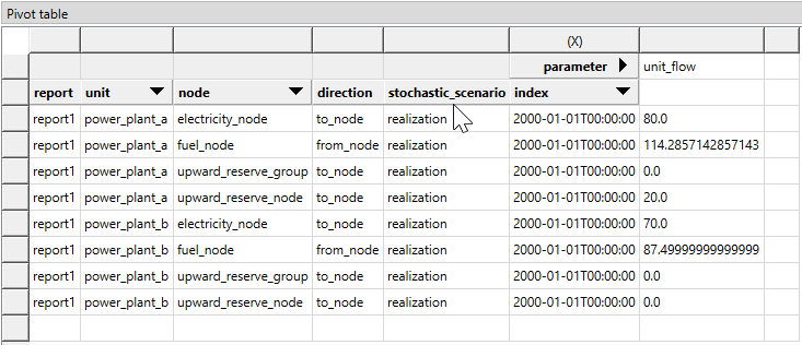
Since the cost of reserve procurement is way cheaper in power_plant_a than in power_plant_b, then the optimal solution is to reduce the production of electricity in power_plant_a to provide reserve with this unit rather than power_plant_b as before. By looking at the total costs, we can see that the reserve procurement costs are no longer zero.